> For the complete documentation index, see [llms.txt](https://taiphoon-com.gitbook.io/taiphoon.com-docs/llms.txt). Markdown versions of documentation pages are available by appending `.md` to page URLs; this page is available as [Markdown](https://taiphoon-com.gitbook.io/taiphoon.com-docs/flight-controller/taiphoon-morakot-flight-controller.md).

# Taiphoon Morakot Flight Controller

Taiphoon Morakot Stack 是專為高性能無人機應用設計的高性能飛塔系統，完全台灣設計與製造。遵循開源的 ArduPilot 與 Betaflight 標準。配備高精度的 IMU、氣壓計與磁羅盤，確保飛行導航與控制的精準度。多用途的外形設計可支援多種機型，讓其在專業任務與極限環境下都能發揮卓越表現。

<figure><img src="https://content.gitbook.com/content/mvFqg0h5Ob1pRXspm7Yi/blobs/feMcV2gXiFC1AQwHsAeo/20260211%20Morakot%20V6%E6%AD%A3%E9%9D%A2.png" alt=""><figcaption></figcaption></figure>

## **規格** Specifications

* **微處理器 Microprocessor**
  * STM32H743VIT MCU
* **感測器 Sensors**
  * ICM-45686 High-Performance IMU
  * Bosch BMP390 Barometer
  * ST IIS2MDCTR Magnetometer
* **電源系統 Power**
  * 3S–8S DC Input power
  * 5V周邊設備電源輸出 BEC peripherals power
  * 12V影像設備電源輸出 BEC video power
* **介面 Interfaces**
  * 8x UART
  * 9x PWM
  * 1x I2C
  * 1x CAN
  * 1x OSD(SPI)
  * 1x USB Type-C Connector
  * 1x Ethernet
  * 1x MicroSD Slot
  * LED電量指示燈 Battery Voltage LED Indicator
  * DFU啟動按鍵 Boot button
  * 支援類比圖傳 Analog video support

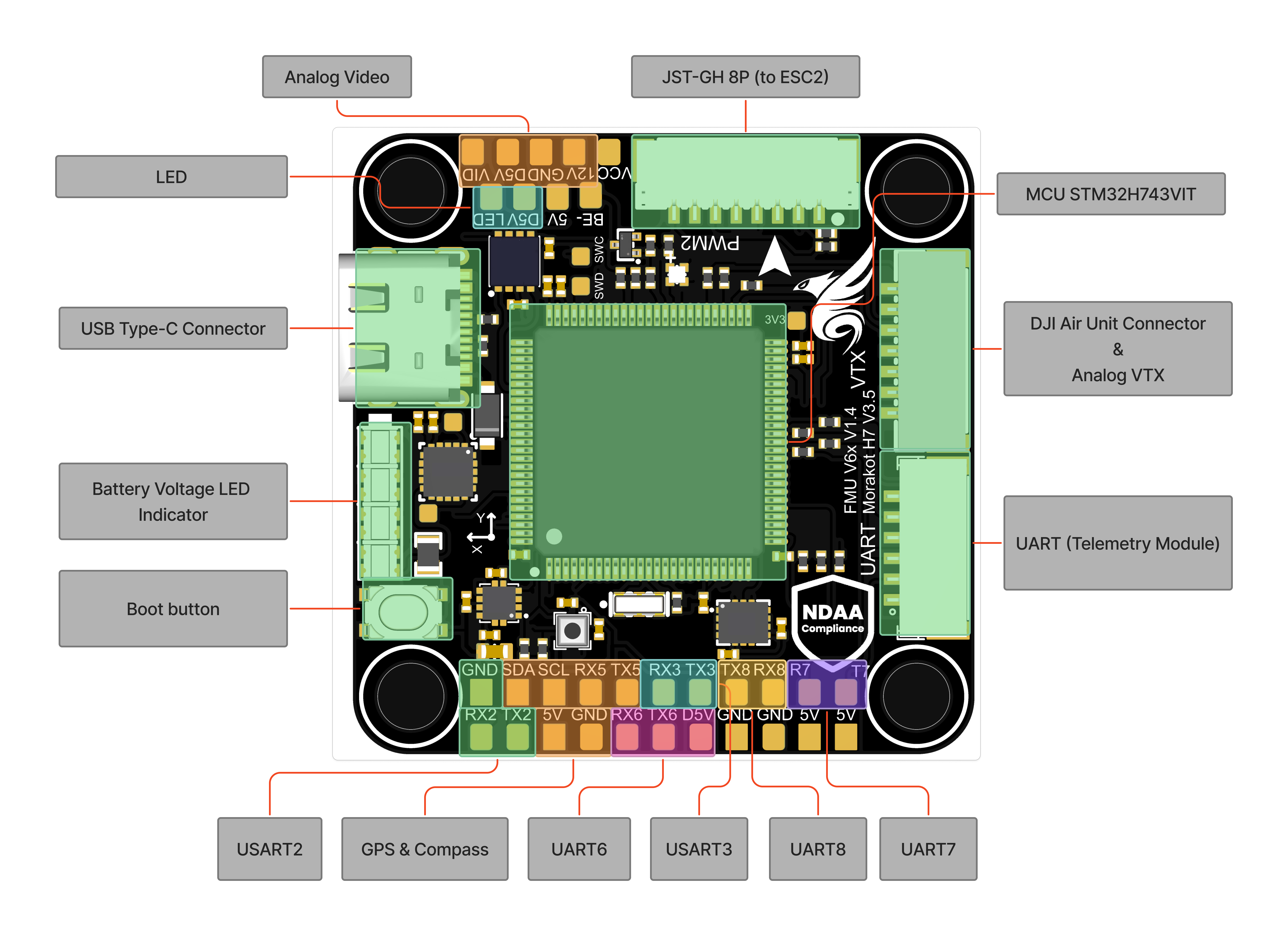
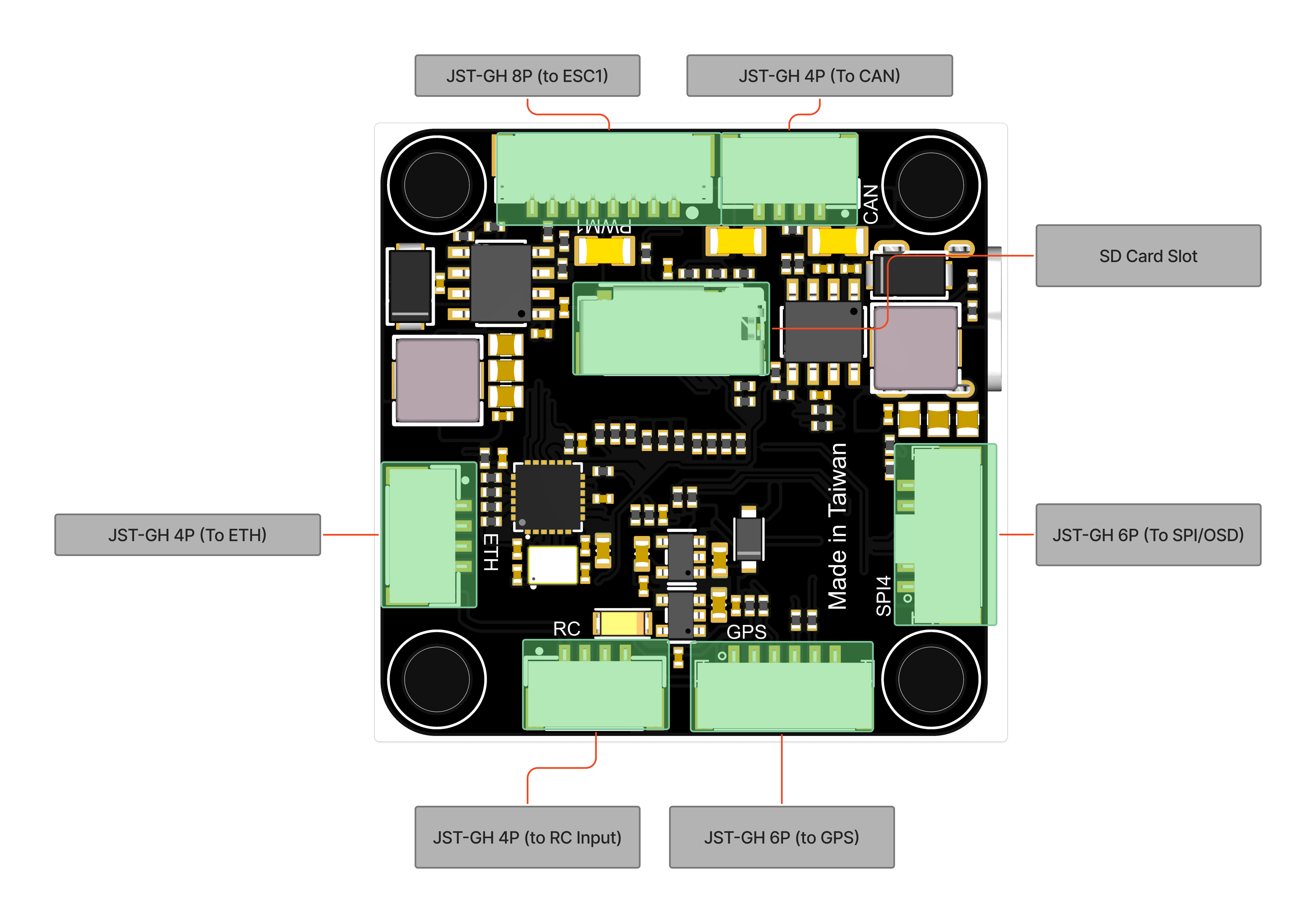
## **接腳定義 Pinout**

<figure><img src="https://content.gitbook.com/content/mvFqg0h5Ob1pRXspm7Yi/blobs/57OAyttZE5ilfpmUgTQ9/20260211%20Morakot%20V6%E6%8E%A5%E5%8F%A3%E5%AE%9A%E7%BE%A9(%E6%AD%A3%E9%9D%A2).png" alt=""><figcaption></figcaption></figure>

<figure><img src="https://content.gitbook.com/content/mvFqg0h5Ob1pRXspm7Yi/blobs/YaxRp7ToqiqwOSKdXdtb/20260211%20Morakot%20V6%E6%8E%A5%E5%8F%A3%E5%AE%9A%E7%BE%A9(%E8%83%8C%E9%9D%A2).png" alt=""><figcaption></figcaption></figure>

## **連接器接腳分配 Connectors Pin A**ssignments

**PWM1(JST-GH 8p)**

| Pin | Signal   | Voltage     |
| --- | -------- | ----------- |
| 1   | VCC      | +12V\~33.6V |
| 2   | UART7 RX | +3.3V       |
| 3   | GND      |             |
| 4   | CURRENT  |             |
| 5   | Motor1   |             |
| 6   | Motor2   |             |
| 7   | Motor3   |             |
| 8   | Motor4   |             |

**PWM2(JST-GH 8p)**

| Pin | Signal  | Voltage     |
| --- | ------- | ----------- |
| 1   | VCC     | +12V\~33.6V |
| 2   | Motor9  | +3.3V       |
| 3   | GND     |             |
| 4   | CURRENT |             |
| 5   | Motor5  |             |
| 6   | Motor6  |             |
| 7   | Motor7  |             |
| 8   | Motor8  |             |

**VTX(JST-GH 7p)**

| Pin | Signal          | Voltage |
| --- | --------------- | ------- |
| 1   | Video           |         |
| 2   | VCC             | +12V    |
| 3   | GND             |         |
| 4   | USART1 RX       | +3.3V   |
| 5   | USART1 TX       | +3.3V   |
| 6   | GND             |         |
| 7   | USART3 RX(SBUS) | +3.3V   |

**UART(JST-GH 6p)**

| Pin | Signal    | Voltage |
| --- | --------- | ------- |
| 1   | VCC       | +5V     |
| 2   | UART7 TX  | +3.3V   |
| 3   | UART7 RX  | +3.3V   |
| 4   | UART7 CTS |         |
| 5   | UART7 RTS |         |
| 6   | GND       |         |

**GPS(JST-GH 6p)**

| Pin | Signal   | Voltage |
| --- | -------- | ------- |
| 1   | VCC      | +5V     |
| 2   | UART5 TX | +3.3V   |
| 3   | UART5 RX | +3.3V   |
| 4   | SCL      |         |
| 5   | SDA      |         |
| 6   | GND      |         |

**OSD(JST-GH 6p)**

| Pin | Signal    | Voltage |
| --- | --------- | ------- |
| 1   | VCC       | +5V     |
| 2   | SPI4 MOSI |         |
| 3   | SPI4 MISO |         |
| 4   | SPI4 SCK  |         |
| 5   | SPI4 CS   |         |
| 6   | GND       |         |

**CAN(JST-GH 4p)**

| Pin | Signal | Voltage |
| --- | ------ | ------- |
| 1   | VCC    | +5V     |
| 2   | CAN\_H |         |
| 3   | CAN\_L |         |
| 4   | GND    |         |

**RC Input(JST-GH 4p)**

| Pin | Signal   | Voltage |
| --- | -------- | ------- |
| 1   | VCC      | +5V     |
| 2   | UART8 RX | +3.3V   |
| 3   | UART8 TX | +3.3V   |
| 4   | GND      |         |

**ETH(JST-GH 4p)**

| Pin | Signal | Voltage |
| --- | ------ | ------- |
| 1   | RXN    |         |
| 2   | RXP    |         |
| 3   | TXN    |         |
| 4   | TXP    |         |

## **UART接口定義 Serial Port Mapping**

<table><thead><tr><th width="145">Serial Number</th><th width="130">UART</th><th width="186">Port</th><th>Ardupilot Parameters</th></tr></thead><tbody><tr><td>Serial0</td><td>OTG1</td><td>USB Type-C</td><td><code>SERIAL0_BAUD</code> = <strong>115</strong><br><code>SERIAL0_PROTOCOL</code> = <strong>2</strong></td></tr><tr><td>Serial1</td><td>USART1</td><td>VTX<br>(compatible with DJI)</td><td><code>SERIAL1_BAUD</code> = <strong>115</strong><br><code>SERIAL1_OPTIONS</code> = <strong>0</strong><br><code>SERIAL1_PROTOCOL</code> = <strong>42</strong></td></tr><tr><td>Serial2</td><td>USART2</td><td>Telem(UART)</td><td><code>SERIAL2_BAUD</code> = <strong>57</strong><br><code>SERIAL2_OPTIONS</code> = <strong>0</strong><br><code>SERIAL2_PROTOCOL</code> = <strong>2</strong></td></tr><tr><td>Serial3</td><td>USART3</td><td>S.BUS</td><td><code>SERIAL3_OPTIONS</code> = <strong>1</strong><br><code>SERIAL3_PROTOCOL</code> = <strong>23</strong></td></tr><tr><td>Serial4</td><td>UART5</td><td>GPS</td><td><code>SERIAL4_BAUD</code> = <strong>230</strong><br><code>SERIAL4_OPTIONS</code> = <strong>0</strong><br><code>SERIAL4_PROTOCOL</code> = <strong>5</strong></td></tr><tr><td>Serial5</td><td>USART6</td><td>ESC1</td><td><code>SERIAL5_BAUD</code> = <strong>115</strong><br><code>SERIAL5_OPTIONS</code> = <strong>0</strong><br><code>SERIAL5_PROTOCOL</code> = <strong>16</strong></td></tr><tr><td>Serial6</td><td>UART7</td><td>Telem(UART)</td><td><code>SERIAL6_BAUD</code> = <strong>115</strong><br><code>SERIAL6_OPTIONS</code> = <strong>0</strong><br><code>SERIAL6_PROTOCOL</code> = <strong>2</strong></td></tr><tr><td>Serial7</td><td>UART8</td><td>RC Input</td><td><code>SERIAL7_OPTIONS</code> = <strong>0</strong><br><code>SERIAL7_PROTOCOL</code> = <strong>23</strong></td></tr></tbody></table>

## **遙控器輸入 RC Input**

RC input經由UART介面輸入遙控訊號，支援CRSF、ELRS、S.BUS等訊號。

### ArduPilot 設定

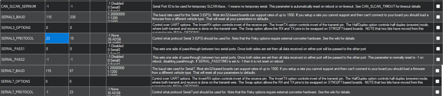
**先依接收機的實際接線選擇下方分頁。** 在 Mission Planner 的 **CONFIG/TUNING → Full Parameter List** 搜尋各參數，填入表格設定值，按 **Write Params** 後重新啟動飛控。

{% tabs %}
{% tab title="使用VTX介面" %}
如果使用**VTX**介面作為RC Input，例如DJI O4 PRO

<figure><img src="https://content.gitbook.com/content/mvFqg0h5Ob1pRXspm7Yi/blobs/I1tkZ4ysD3lFFWD3wEoA/image.png" alt=""><figcaption></figcaption></figure>

| 參數名稱               | 設定值     | 用途             |
| ------------------ | ------- | -------------- |
| `SERIAL7_BAUD`     | **115** | RC 介面傳輸速率。     |
| `SERIAL7_OPTIONS`  | **0**   | RC 介面串列選項。     |
| `SERIAL7_PROTOCOL` | **-1**  | 關閉 RC 介面的接收功能。 |
| `SERIAL3_BAUD`     | **115** | VTX 接收介面傳輸速率。  |
| `SERIAL3_OPTIONS`  | **1**   | 啟用接收訊號反相。      |
| `SERIAL3_PROTOCOL` | **23**  | 啟用 RC 輸入。      |

**可複製的參數清單**

```
SERIAL7_BAUD,115
SERIAL7_OPTIONS,0
SERIAL7_PROTOCOL,-1
SERIAL3_BAUD,115
SERIAL3_OPTIONS,1
SERIAL3_PROTOCOL,23
```

{% endtab %}

{% tab title="使用RC介面" %}
如果使用**RC**介面作為RC Input，例如ELRS、SBUS等

<figure><img src="https://content.gitbook.com/content/mvFqg0h5Ob1pRXspm7Yi/blobs/IlAHe9abDHtbKHEd2RLH/image.png" alt=""><figcaption></figcaption></figure>

| 參數名稱               | 設定值     | 用途              |
| ------------------ | ------- | --------------- |
| `SERIAL3_BAUD`     | **115** | VTX 接收介面傳輸速率。   |
| `SERIAL3_OPTIONS`  | **0**   | VTX 接收介面串列選項。   |
| `SERIAL3_PROTOCOL` | **-1**  | 關閉 VTX 介面的接收功能。 |
| `SERIAL7_BAUD`     | **115** | RC 介面傳輸速率。      |
| `SERIAL7_OPTIONS`  | **0**   | RC 介面串列選項。      |
| `SERIAL7_PROTOCOL` | **23**  | 啟用 RC 輸入。       |

**可複製的參數清單**

```
SERIAL3_BAUD,115
SERIAL3_OPTIONS,0
SERIAL3_PROTOCOL,-1
SERIAL7_BAUD,115
SERIAL7_OPTIONS,0
SERIAL7_PROTOCOL,23
```

{% endtab %}
{% endtabs %}

### Betaflight

使用VTX介面的RX作為RC input

<figure><img src="https://content.gitbook.com/content/mvFqg0h5Ob1pRXspm7Yi/blobs/YIV1Vlg7p0DrckmTZrNb/image.png" alt=""><figcaption></figcaption></figure>

## **網路設定 Ethernet**

<figure><img src="https://content.gitbook.com/content/mvFqg0h5Ob1pRXspm7Yi/blobs/3881FmGst9o6yRpiRS62/image.png" alt=""><figcaption></figcaption></figure>

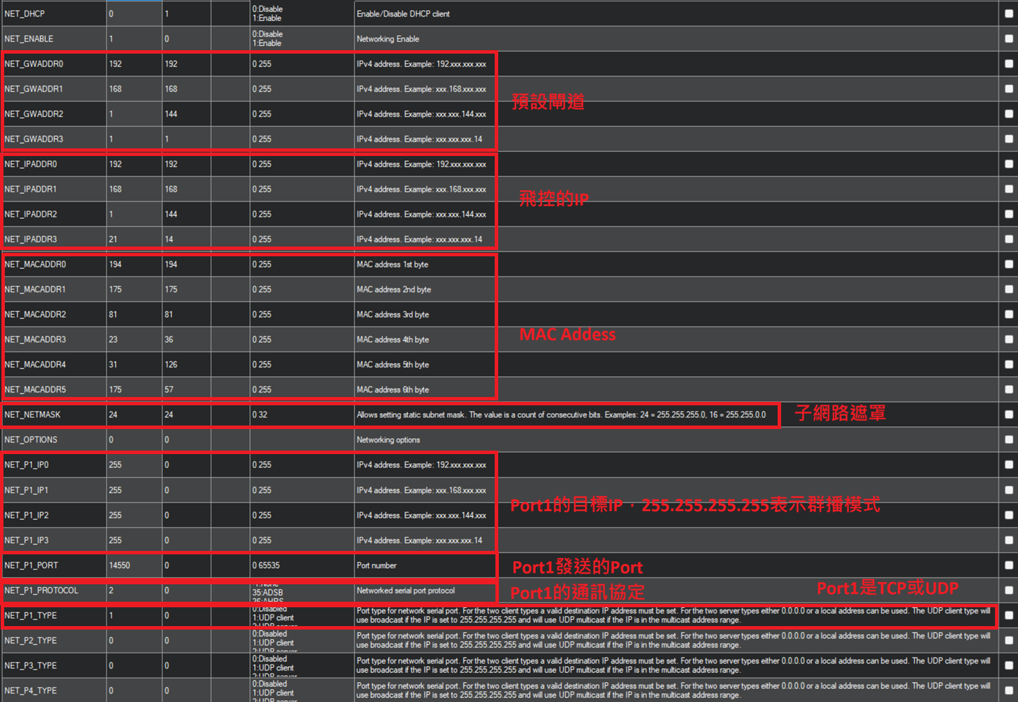
**以下為固定 IP 設定範例：飛控 IP 為 192.168.1.21，閘道為 192.168.1.1。** 請依實際網段調整 IP 與閘道。

| 參數名稱              | 設定值       |
| ----------------- | --------- |
| `NET_DHCP`        | **0**     |
| `NET_ENABLE`      | **1**     |
| `NET_GWADDR0`     | **192**   |
| `NET_GWADDR1`     | **168**   |
| `NET_GWADDR2`     | **1**     |
| `NET_GWADDR3`     | **1**     |
| `NET_IPADDR0`     | **192**   |
| `NET_IPADDR1`     | **168**   |
| `NET_IPADDR2`     | **1**     |
| `NET_IPADDR3`     | **21**    |
| `NET_NETMASK`     | **24**    |
| `NET_OPTIONS`     | **0**     |
| `NET_P1_IP0`      | **255**   |
| `NET_P1_IP1`      | **255**   |
| `NET_P1_IP2`      | **255**   |
| `NET_P1_IP3`      | **255**   |
| `NET_P1_PORT`     | **14550** |
| `NET_P1_PROTOCOL` | **2**     |
| `NET_P1_TYPE`     | **1**     |
| `NET_P2_TYPE`     | **0**     |
| `NET_P3_TYPE`     | **0**     |
| `NET_P4_TYPE`     | **0**     |

在 **Full Parameter List** 設定後，按 **Write Params** 儲存。

**可複製的參數清單**

```
NET_DHCP,0
NET_ENABLE,1
NET_GWADDR0,192
NET_GWADDR1,168
NET_GWADDR2,1
NET_GWADDR3,1
NET_IPADDR0,192
NET_IPADDR1,168
NET_IPADDR2,1
NET_IPADDR3,21
NET_NETMASK,24
NET_OPTIONS,0
NET_P1_IP0,255
NET_P1_IP1,255
NET_P1_IP2,255
NET_P1_IP3,255
NET_P1_PORT,14550
NET_P1_PROTOCOL,2
NET_P1_TYPE,1
NET_P2_TYPE,0
NET_P3_TYPE,0
NET_P4_TYPE,0
```

## **CAN 設定**

<figure><img src="https://content.gitbook.com/content/mvFqg0h5Ob1pRXspm7Yi/blobs/grcJ3tUBjfy9GAFGCCmE/image.png" alt=""><figcaption></figcaption></figure>

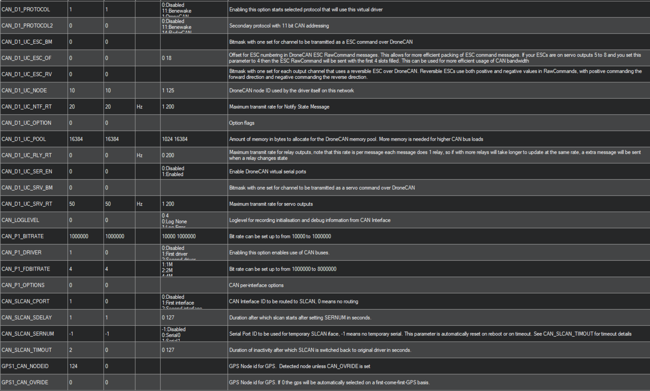
**使用 ArduPilot 時，在 Full Parameter List 設定以下參數。** 按 **Write Params** 儲存。

| 參數名稱              | 設定值   | 用途             |
| ----------------- | ----- | -------------- |
| `CAN_P1_DRIVER`   | **1** | CAN1 使用驅動程式 1。 |
| `CAN_D1_PROTOCOL` | **1** | 驅動程式 1 的協定設定。  |

**可複製的參數清單**

```
CAN_P1_DRIVER,1
CAN_D1_PROTOCOL,1
```