> For the complete documentation index, see [llms.txt](https://taiphoon-com.gitbook.io/taiphoon.com-docs/llms.txt). Markdown versions of documentation pages are available by appending `.md` to page URLs; this page is available as [Markdown](https://taiphoon-com.gitbook.io/taiphoon.com-docs/ja/products/flight-controller/taiphoon-morakot-flight-controller.md).

# Taiphoon Morakot Flight Controller

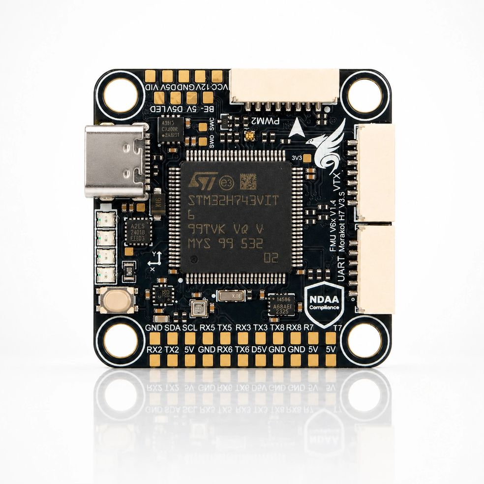
Taiphoon Morakot Stack は高性能ドローン専用設計の高性能スタックシステムで、完全に台湾で設計・製造されています。オープンソースの ArduPilot と Betaflight の標準に準拠し、高精度な IMU、気圧計、コンパスを搭載して飛行ナビゲーションと制御の精度を確保します。多用途な形状設計で多様な機体に対応し、専門的な任務や過酷な環境でも優れた性能を発揮します。

<figure><img src="https://content.gitbook.com/content/Cz4IZEBqCk5SBHtJan7e/blobs/AzEwMyIiP3kC9GuqAaF0/Morakot%20FC%20%E5%AE%98%E7%B6%B2%E7%94%A2%E5%93%81%E5%9C%96.jpg" alt=""><figcaption></figcaption></figure>

## **仕様** Specifications

* **マイクロプロセッサー Microprocessor**
  * STM32H743VIT MCU
* **センサー Sensors**
  * ICM-45686 High-Performance IMU
  * Bosch BMP390 Barometer
  * ST IIS2MDCTR Magnetometer
* **電源システム Power**
  * 3S–8S DC Input power
  * 5V周辺機器用電源出力 BEC peripherals power
  * 12V映像機器用電源出力 BEC video power
* **インターフェース Interfaces**
  * 8x UART
  * 9x PWM
  * 1x I2C
  * 1x CAN
  * 1x OSD(SPI)
  * 1x USB Type-C Connector
  * 1x Ethernet
  * 1x MicroSD Slot
  * LEDバッテリー残量インジケーター Battery Voltage LED Indicator
  * DFU起動ボタン Boot button
  * アナログ映像送信対応 Analog video support

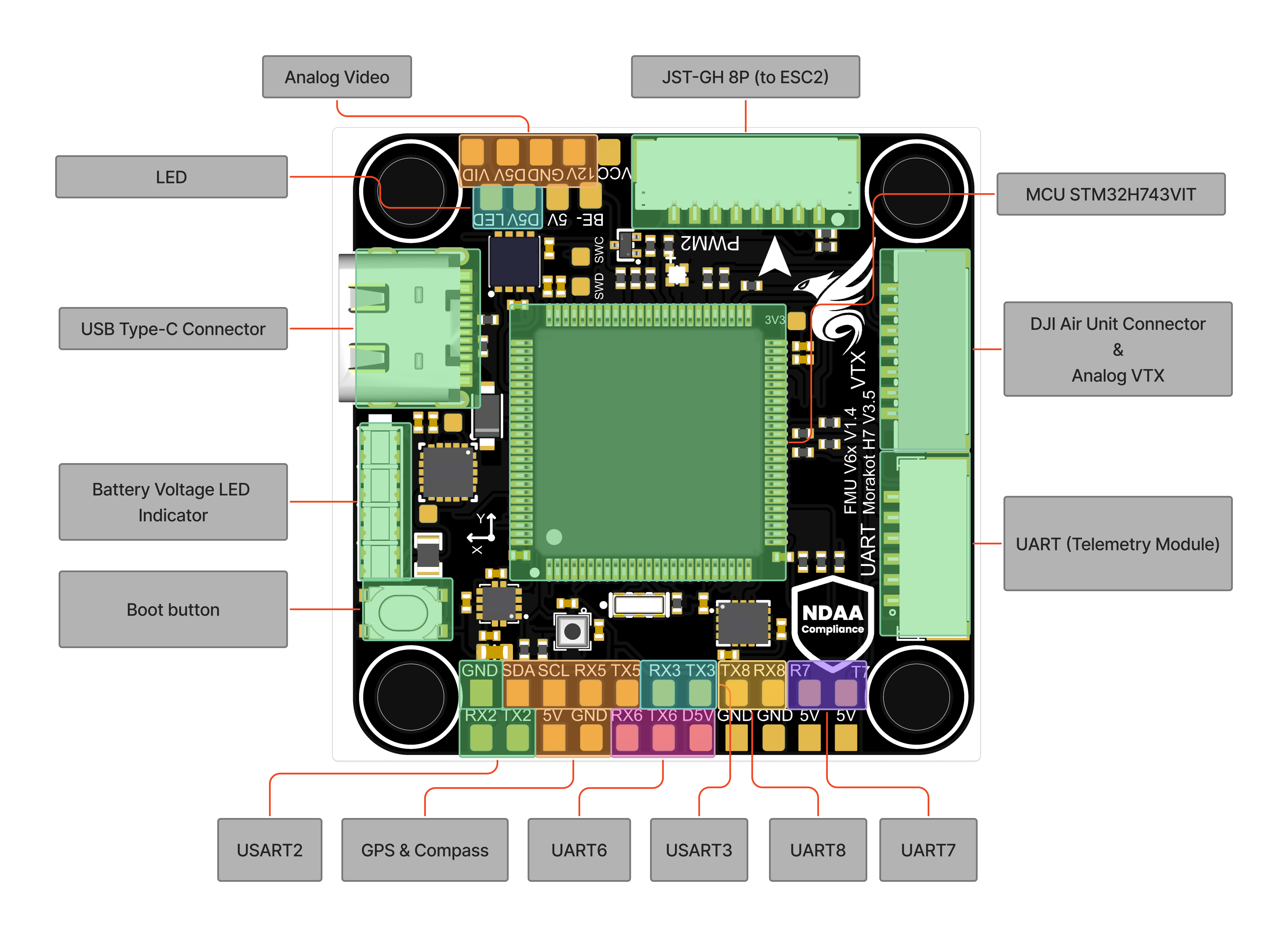
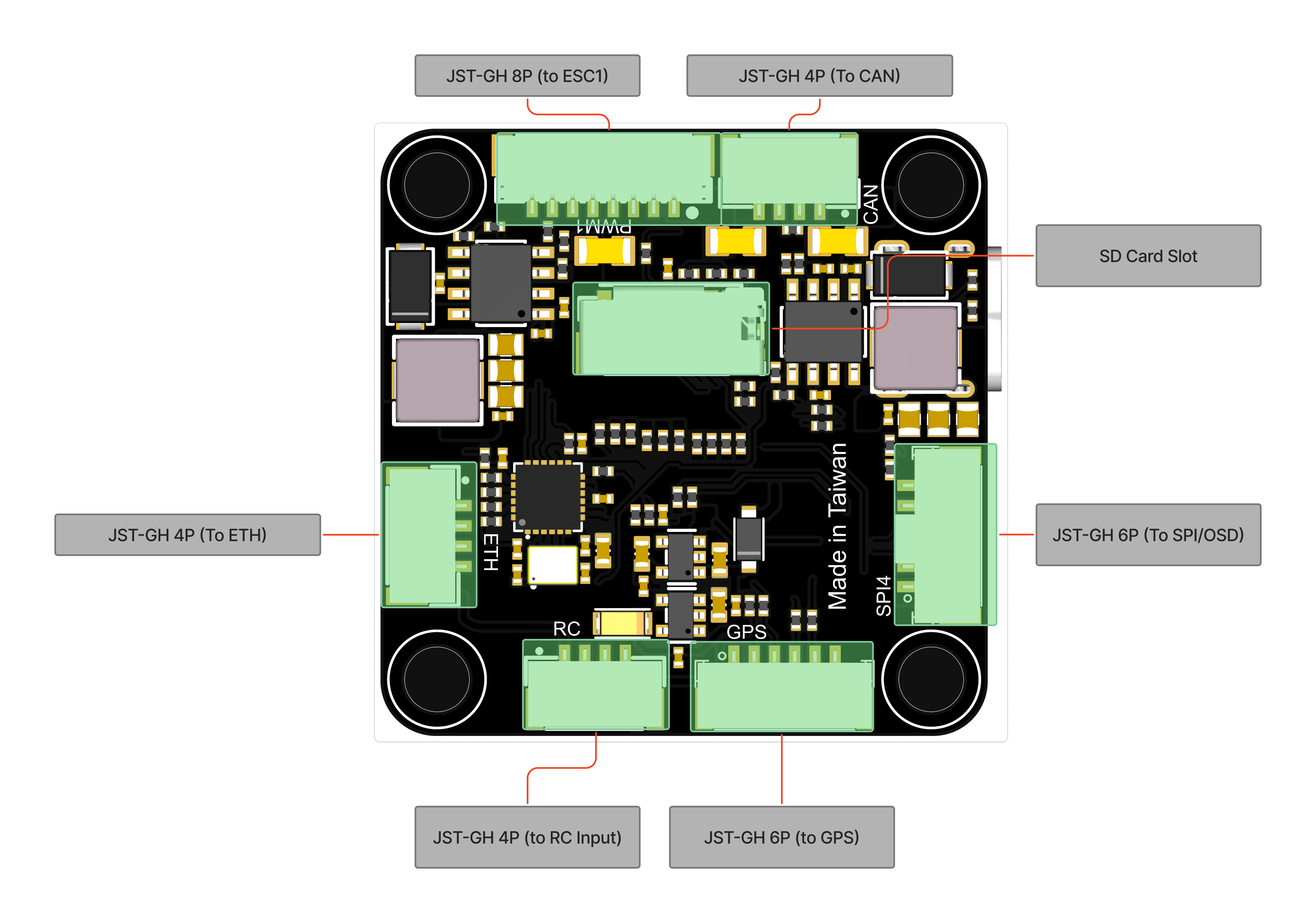
## **ピン定義 Pinout**

<figure><img src="https://content.gitbook.com/content/Cz4IZEBqCk5SBHtJan7e/blobs/XrVYewYyYu9v8A6XtbuP/20260211%20Morakot%20V6%E6%8E%A5%E5%8F%A3%E5%AE%9A%E7%BE%A9(%E6%AD%A3%E9%9D%A2).png" alt=""><figcaption></figcaption></figure>

<figure><img src="https://content.gitbook.com/content/Cz4IZEBqCk5SBHtJan7e/blobs/3a2HEqFEDJwe0iRpJga7/20260211%20Morakot%20V6%E6%8E%A5%E5%8F%A3%E5%AE%9A%E7%BE%A9(%E8%83%8C%E9%9D%A2).png" alt=""><figcaption></figcaption></figure>

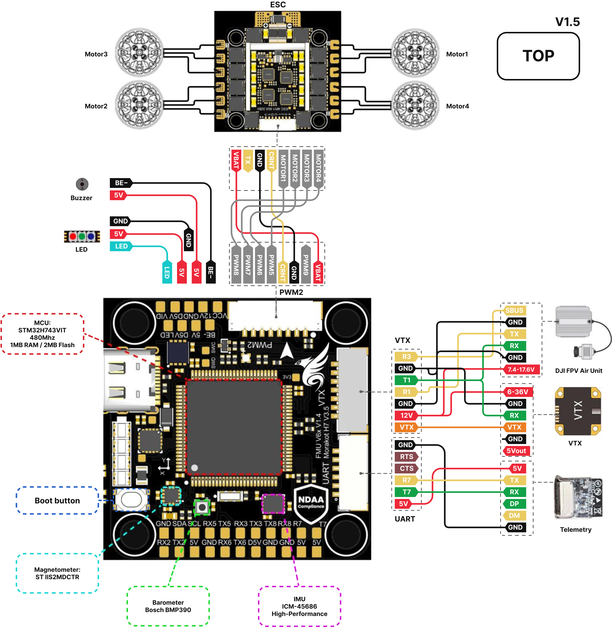
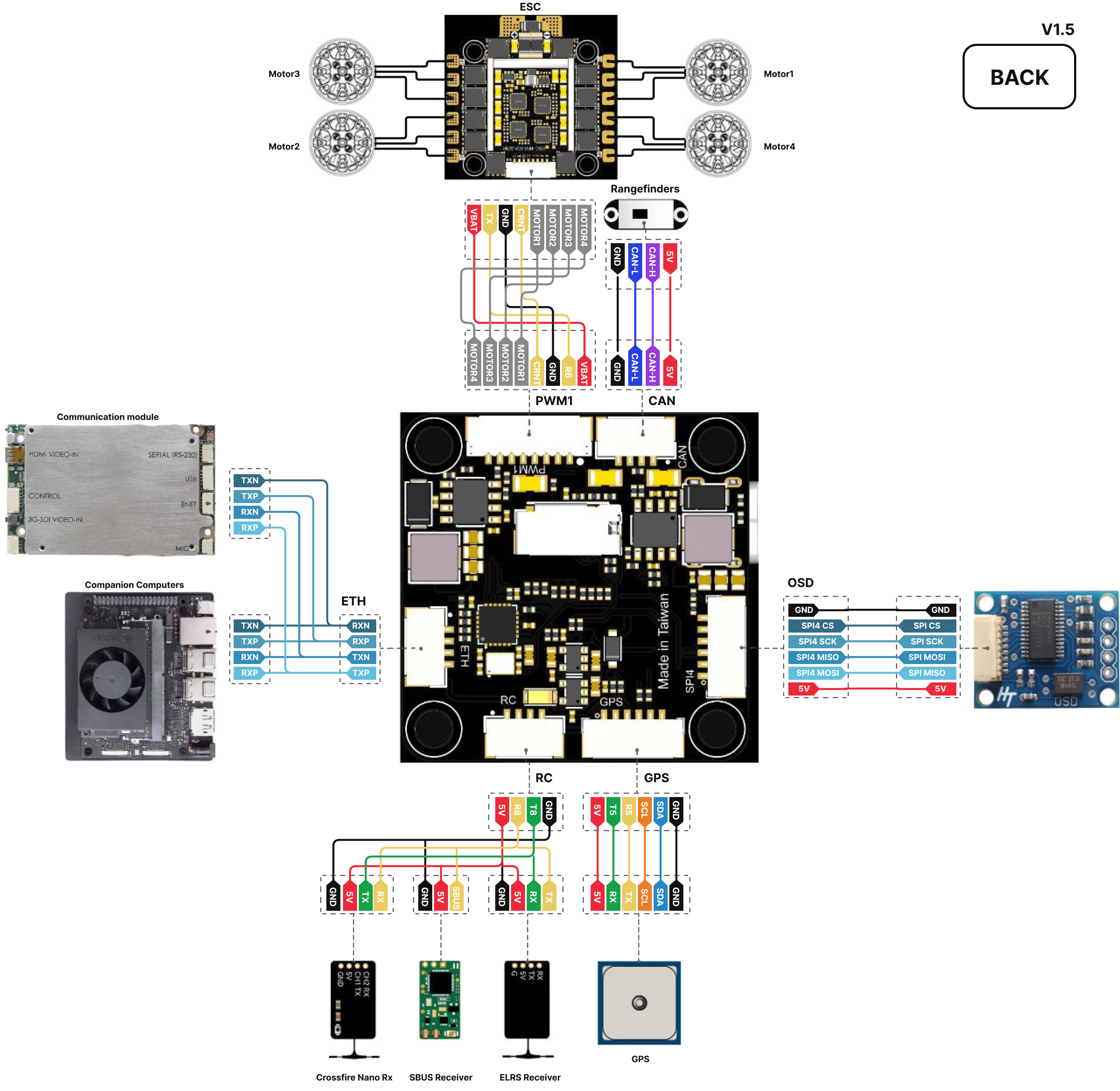
## 周辺機器配線図 Peripherals Wiring Diagram

<div><figure><img src="https://content.gitbook.com/content/Cz4IZEBqCk5SBHtJan7e/blobs/NUBjmezD7WxCVVXE1fWG/Morakot_top_Wired.jpg" alt=""><figcaption></figcaption></figure> <figure><img src="https://content.gitbook.com/content/Cz4IZEBqCk5SBHtJan7e/blobs/jmAuk6OUnwbSf29OXaoV/Morakot_bottom_Wired.jpg" alt=""><figcaption></figcaption></figure></div>

## **コネクターのピン割り当て Connectors Pin A**ssignments

**PWM1(JST-GH 8p)**

| Pin | Signal   | Voltage     |
| --- | -------- | ----------- |
| 1   | VCC      | +12V\~33.6V |
| 2   | UART7 RX | +3.3V       |
| 3   | GND      |             |
| 4   | CURRENT  |             |
| 5   | Motor1   |             |
| 6   | Motor2   |             |
| 7   | Motor3   |             |
| 8   | Motor4   |             |

**PWM2(JST-GH 8p)**

| Pin | Signal  | Voltage     |
| --- | ------- | ----------- |
| 1   | VCC     | +12V\~33.6V |
| 2   | Motor9  | +3.3V       |
| 3   | GND     |             |
| 4   | CURRENT |             |
| 5   | Motor5  |             |
| 6   | Motor6  |             |
| 7   | Motor7  |             |
| 8   | Motor8  |             |

**VTX(JST-GH 7p)**

| Pin | Signal          | Voltage |
| --- | --------------- | ------- |
| 1   | Video           |         |
| 2   | VCC             | +12V    |
| 3   | GND             |         |
| 4   | USART1 RX       | +3.3V   |
| 5   | USART1 TX       | +3.3V   |
| 6   | GND             |         |
| 7   | USART3 RX(SBUS) | +3.3V   |

**UART(JST-GH 6p)**

| Pin | Signal    | Voltage |
| --- | --------- | ------- |
| 1   | VCC       | +5V     |
| 2   | UART7 TX  | +3.3V   |
| 3   | UART7 RX  | +3.3V   |
| 4   | UART7 CTS |         |
| 5   | UART7 RTS |         |
| 6   | GND       |         |

**GPS(JST-GH 6p)**

| Pin | Signal   | Voltage |
| --- | -------- | ------- |
| 1   | VCC      | +5V     |
| 2   | UART5 TX | +3.3V   |
| 3   | UART5 RX | +3.3V   |
| 4   | SCL      |         |
| 5   | SDA      |         |
| 6   | GND      |         |

**OSD(JST-GH 6p)**

| Pin | Signal    | Voltage |
| --- | --------- | ------- |
| 1   | VCC       | +5V     |
| 2   | SPI4 MOSI |         |
| 3   | SPI4 MISO |         |
| 4   | SPI4 SCK  |         |
| 5   | SPI4 CS   |         |
| 6   | GND       |         |

**CAN(JST-GH 4p)**

| Pin | Signal | Voltage |
| --- | ------ | ------- |
| 1   | VCC    | +5V     |
| 2   | CAN\_H |         |
| 3   | CAN\_L |         |
| 4   | GND    |         |

**RC Input(JST-GH 4p)**

| Pin | Signal   | Voltage |
| --- | -------- | ------- |
| 1   | VCC      | +5V     |
| 2   | UART8 RX | +3.3V   |
| 3   | UART8 TX | +3.3V   |
| 4   | GND      |         |

**ETH(JST-GH 4p)**

| Pin | Signal | Voltage |
| --- | ------ | ------- |
| 1   | RXN    |         |
| 2   | RXP    |         |
| 3   | TXN    |         |
| 4   | TXP    |         |

## **UARTインターフェース定義 Serial Port Mapping** <a href="#uart-jie-kou-ding-yi-serial-port-mapping" id="uart-jie-kou-ding-yi-serial-port-mapping"></a>

<table><thead><tr><th width="130">UART</th><th width="140">Port on Board</th><th width="145">ArduPilot Serials</th><th>PX4</th><th>Betaflight</th></tr></thead><tbody><tr><td>OTG1</td><td>USB Type-C</td><td>Serial0</td><td>USB</td><td>USB VCP（MSP）</td></tr><tr><td>USART1</td><td>VTX</td><td>Serial1</td><td>TELEM 1</td><td>UART1</td></tr><tr><td>USART2</td><td>None</td><td>Serial2</td><td>TELEM 2</td><td>UART2</td></tr><tr><td>USART3</td><td>S.BUS</td><td>Serial3</td><td>TELEM 3</td><td>UART3</td></tr><tr><td>UART5</td><td>GPS</td><td>Serial4</td><td>GPS 1</td><td>UART5（GPS）</td></tr><tr><td>USART6</td><td>PWM1</td><td>Serial5</td><td>TELEM/SERIAL 4</td><td>UART6（ESC テレメトリー）</td></tr><tr><td>UART7</td><td>UART</td><td>Serial6</td><td>Wifi Port</td><td>UART7</td></tr><tr><td>UART8</td><td>RC Input</td><td>Serial7</td><td>Radio Controller</td><td>UART8（Serial RX）</td></tr></tbody></table>

## **送信機入力 RC Input**

RC input は UART インターフェースを介して送信機の信号を入力し、CRSF、ELRS、S.BUS などの信号に対応しています。

## ファームウェア設定

RC Input、ネットワーク、CAN などのファームウェア設定については、使用するファームウェアに応じて、対応するプラットフォームのガイドに進んでください。

<table data-view="cards"><thead><tr><th></th><th></th><th data-hidden data-card-target data-type="content-ref"></th><th data-hidden data-card-cover data-type="image">Cover image</th></tr></thead><tbody><tr><td><strong>ArduPilot</strong></td><td>Mission Planner を使用したファームウェアの書き込みと初回設定。RC Input、ネットワーク（Ethernet）、CAN の設定を含みます。</td><td><a href="/taiphoon.com-docs/ja/firmware/ardupilot.md">ArduPilot</a></td><td data-object-fit="contain"><a href="https://content.gitbook.com/content/Cz4IZEBqCk5SBHtJan7e/blobs/NTCTL7VMP7xDT8dX4TaC/taiphoon-ardupilot-cover.png">taiphoon-ardupilot-cover.png</a></td></tr><tr><td><strong>PX4</strong></td><td>QGroundControl を使用したファームウェアの書き込みと初回設定。</td><td><a href="/taiphoon.com-docs/ja/firmware/px4.md">PX4</a></td><td data-object-fit="contain"><a href="https://content.gitbook.com/content/Cz4IZEBqCk5SBHtJan7e/blobs/mtQhza6bGsqDHKmPbGug/taiphoon-px4-cover.png">taiphoon-px4-cover.png</a></td></tr><tr><td><strong>Betaflight</strong></td><td>Betaflight App を使用したファームウェアの書き込みと初回設定。ポートと受信機の設定を含みます。</td><td><a href="/taiphoon.com-docs/ja/firmware/betaflight.md">Betaflight</a></td><td data-object-fit="contain"><a href="https://content.gitbook.com/content/Cz4IZEBqCk5SBHtJan7e/blobs/yBzIRQKLpRjsnRvWfwlv/taiphoon-betaflight-cover.png">taiphoon-betaflight-cover.png</a></td></tr></tbody></table>